FSK Modulation and Demodulation Study
Uploaded by
Mrigya JainFSK Modulation and Demodulation Study
Uploaded by
Mrigya Jain- Frequency Shift Keying Theory
- Experiment Overview
- FSK Modulator
- FSK Demodulator and Modulation Advantages
- Experiment Procedure
- Observations and Data Analysis
- Conclusion
Common questions
Powered by AIThe amplitude of the FSK waveform is adjusted to ensure that the output signal is clear and strong enough for detection and processing. This adjustment affects the signal's robustness against channel attenuation, enabling successful demodulation and recovery of the data at the output without errors caused by insufficient signal level.
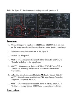
The key steps include: connecting the power supplies for ST2156 and ST2157 without turning them on initially, making the required connections as shown in the given diagram (figure 3.1), switching on the power, connecting the oscilloscope to various test points to observe waveforms, and adjusting the potentiometers on the modulator circuit to set the amplitude of the FSK waveform.
Using higher frequencies in FSK modulation results in a wider bandwidth requirement, which narrows the channel capacity within a given frequency band. While higher frequencies may improve performance in terms of data rate and error resilience due to lower susceptibility to certain types of noise, they reduce the total number of available communication channels because of increased bandwidth consumption.
FSK is more reliable than ASK in noisy and fading channels because the amplitude change in FSK does not impact data integrity, unlike in ASK where amplitude changes are used to represent data bits. This makes FSK less susceptible to noise interference that can affect amplitude.
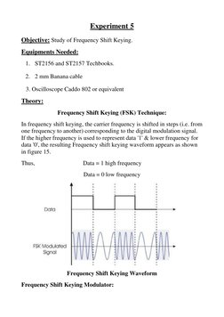
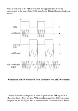
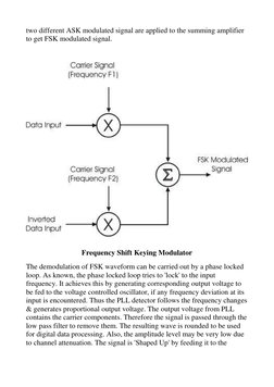
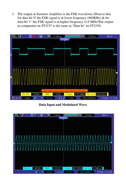
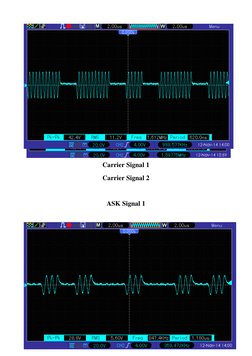
FSK modulation can be generated using two amplitude shift keying (ASK) modulators, each with a different carrier frequency. The digital data signal is inverted in one of the modulators. The outputs of these two modulators are then summed using a summing amplifier to generate the FSK-modulated waveform. This method effectively combines the high frequency for data '1' and low frequency for data '0' to create the FSK signal.
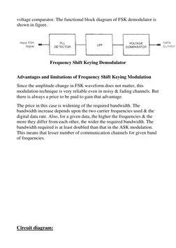
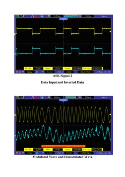
The components necessary for FSK demodulation include the phase locked loop (PLL), a low pass filter, and a voltage comparator. The PLL locks to the input frequency and adjusts its oscillator based on any detected frequency deviations, providing an output voltage indicative of the frequency shifts. The low pass filter removes the high-frequency carrier components, leaving the baseband signal. The voltage comparator shapes the filtered output, restoring it to the appropriate digital logic levels for data processing.
The FSK modulator can be used at the transmitter side to convert digital data into an FSK-modulated signal suitable for transmission over a physical medium, such as wireless or wired channels. The demodulator is used at the receiver side to recover the original digital data from the received FSK-modulated signal. This modulation-demodulation process is critical in systems like mobile communications, telemetry, and remote control applications, where reliable data transmission despite channel noise is essential.
The trade-off for FSK's reliability in noisy channels is the need for a larger bandwidth, as FSK requires a bandwidth at least double that of ASK. This is because FSK uses two different frequencies to represent binary data, and as these frequencies increase and diverge, the required bandwidth widens, reducing the number of channels available within a given frequency band.
Increasing the difference between the two carrier frequencies in FSK modulation leads to a wider required bandwidth. This is because the larger the frequency difference, the greater the spectrum occupied by the signal, thus necessitating more channel space for proper transmission.
In FSK demodulation, the phase locked loop (PLL) plays a crucial role by attempting to lock to the input frequency of the FSK signal. Whenever the input frequency deviates, the PLL produces a corresponding output voltage, adjusting the voltage controlled oscillator accordingly. This process allows the PLL to track frequency changes, and the resulting output voltage is then filtered to remove carrier components, producing a signal suitable for digital data processing.