Bode Plots in Control System
Last Updated :
21 Apr, 2025
Bode plots describe the linear time-invariant systems' frequency response (change in magnitude and phase as a function of frequency). It helps in analyzing the stability of control system. It applies to the minimum phase transfer function i.e. (poles and zeros should be in the left half of the s-plane).
In this article, we are going to learn what is Bode Plot and Types of Bode Plots and how to draw Blode plot and parameters of Bode plot, we are going to learn what is Phase and Gain Margin and what are the advantages and disadvantages of Bode plots in Control System.
What are Bode Plots?
A graph is called as Bode plot which is frequently used in control system engineering to assess a control system's stability. Two graphs, the Bode phase plot (which expresses the phase shift in degrees) and the Bode magnitude plot (which expresses the magnitude in decibels), are used to map the frequency response of the system.
Hendrik Wade Bode first introduced Bode plots in the 1930s while he was employed by Bell Laboratories in the United States. Bode plots, unlike the Nyquist stability criterion, can handle transfer functions with right half plane singularities, despite being a reasonably straightforward approach for calculating system stability.
Types of Bode Plot
1. Gain plot:
It represents the magnitude response of the system as a function of frequency. It is plotted on a logarithmic scale.

2. Phase plot:
It depicts the frequency-dependent phase shift of the system's output signal compared to its input signal. It's also drawn on a logarithmic scale.

Bode plot representation for the open loop system is:
20 log|G(jω)|
How to draw Bode Plot?
Step 1: Write the given transfer function in the standard form.
Transfer function:
G(s)= \frac{(s+a)(s+b)}{(s+p)(s+q)}
----- (1)
Standard form of equation 1:
G(s) = \frac{ab(1+ \frac{s}{a})(1+\frac{s}{b})}{pq (1+\frac{s}{p})(1+\frac{s}{q})}
Take \frac{ab}{pq}
as a constant k.
Step 2: Identify the slope of the first line for the bode plot. The slope of the first line is based on poles and zeros at the origin. Refer to the following table.
Poles at origin
| Slope of 1st line
|
|---|
1
| -20 dB/decay
|
2
| -40 dB/decay
|
Zeros at origin
| The slope of 1st line
|
1
| +20 dB/ decay
|
2
| +40 dB/ decay
|
Step 3: Find the gain of 1st line at ω=1 rad/sec
Gain|ω=1 = 20 log k
Where k = \frac{ab}{pq}
Step 4: Write all the corner frequencies in ascending order and define the slope of each line
Step 5: Write the phase equation and make a table of phase and frequency.
Φ = tan-1(\frac{w}{a}
) + tan-1(\frac{w}{b}
) - tan-1(\frac{w}{p}
) - tan-1(\frac{w}{q}
)
How to read Bode Plots?
Blode plots show the frequency response, that is, the changes in magnitude and phase as a function of frequency.
Parameters of Bode Plot
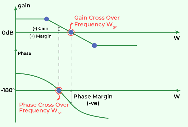
Figure 1 shows the gain and phase plot. The gain cross over frequency (wpc) and phase crossover frequency (wpc) can be calculated using gain plot and phase plot respectively.
Wgc is the value at 0dB whereas Wpc is the value at -180o.
Phase margin and gain can be calculated by extending the graph as shown in the figure.
Stability by bode plot:
 ωpc > ωgc ->System is stable
 ωpc < ωgc ->System is unstable
ωpc = ωgc ->System is marginally stable
Phase and Gain Margins
Phase Margin
The phase margin indicates how much more phases shift we may put in the open loop transfer function before our system becomes unstable.
It can be calculated from the phase at the gain cross-over frequency.
Phase Margin (PM) = 180∘+∠G(jω)H(jω)∣ω=ωgc
= -180∘
Gain crossover frequency:
It is the frequency at which the magnitude of G(s) H(s) is unity as seen in the figure 1.
|G(jω)H(jω)|ω=ωgc = 1
Gain Margin
The gain margin is the amount of open loop gain that can be increased before our system becomes unstable.
It can be calculated from the gain at the phase cross-over frequency.
Gain Margin (GM): \frac{1}{|G(jw)H(jw)|}_{w=w_{pc}}
Phase crossover frequency:
It is the frequency where the phase angle of G(s) H(s) is -180 degrees as seen in the figure 1.
∠G(jω)H(jω)∣ω=ωpc= -180∘
Advantages of Bode Plots in Control System
- It helps in identifying the stability of the system.
- It helps in identifying phases and gaining margins with minimum calculation.
- It can be used to calculate the system's transfer function.
- It can show the amplification and attenuation in the gain plot which is helpful in designing the filters.
Disadvantages of Bode Plots in Control System
- It is only applicable to LTI (linear time-invariant) system.
- It is not suitable for the system having extremely high or low frequencies.
- It focuses on the frequency response without considering the transient time effect.
Solved Examples of Bode Plots
Example: Find the transfer function from the bode plot given in the figure?

Solution:
Step 1: Corner frequency: ω= 1, 10, 100
Step 2: Calculation of the slope
Slope
| Increasing or decreasing
|
|---|
0 dB/dec
| Initial value
|
+20 dB/dec
| Increasing
|
0 dB/dec
| Decreasing
|
-20 dB/dec
| Decreasing
|
Therefore, if the slope is increasing then it is a zero else it is a pole.
ω = 1 (zeros)
ω = 1 (pole)
ω = 1 (pole)
Step 3: Calculating the gain of the first line at ω = 1
Gain = 20 log(k) + (slope of 1st line) log(ω)
-20    = 20log(k) + 0
  k       = 0.1
Step 4: Writing the transfer function
T(s) = \frac{k(1+\frac{s}{1})}{(1+\frac{s}{10})(1+\frac{s}{100} )}
k= 0.1
T(s) = \frac{0.1(1+\frac{s}{1})}{(1+\frac{s}{10})(1+\frac{s}{100} )}
T(s) = \frac{100(s+1)}{(s+10)(s+100)}
Conclusion
In Conclusion, The Bode plots are similar to the asymptotic Bode plots since they display the magnitude and also the phase plots as straight lines. The Bode plots will only differ in that they will use simple curves rather than straight lines. For other terms of the open loop transfer function that are listed in the table, you can also create the required Bode graphs.
Similar Reads
Control System Tutorial In this Control System tutorial, we will analyze and understand the concept and applications of a Control System with the help of detailed modules. This tutorial covers each module from the basics to advanced, including features, examples, classifications, applications, advantages, disadvantages, an
9 min read
Introduction to Control Systems
What is Control System? Definition, Types, and ExamplesControl systems are used in a wide range of applications they are the essential parts of many modern devices and systems. In simple terms, Control systems are used to control the behavior of devices or any process. In this article, we will be discussing the topic of Control Systems. We will cover th
9 min read
Types of Control SystemsEvery activity in our daily lives is affected by some form of control system. The concept of a control system also plays an important role in the working of space vehicles, satellites, guided missiles, etc. Such control systems are now an integral part of modern industrialization, industrial process
7 min read
Components of Control SystemsWith the advancement of technology, Human dependency on control system have increased over years and are being used everywhere, playing significant role in our daily lives. Contributing to different applications, they made the work easier by reducing human effort and involvement. They are used to co
8 min read
Classification of Control SystemsIn electronics, control systems are grouped into different types, and each has its unique features and uses. They are Important in electronics engineering for regulating dynamic systems, ensuring stability, accuracy, and top performance in various applications. Understanding their classifications he
15+ min read
Uses of Control SystemControl systems have become a necessary part of our day-to-day lives. There is hardly any field where the control systems are not used. They play a very major role in many sectors by making the process much simpler. They are used in fields like transportation, healthcare, aerospace, etc. In this art
8 min read
Advantages and Disadvantages of Control SystemsControl systems play a significant role in our daily lives, impacting various applications that often go unnoticed by us. They are used to control the behavior of devices and systems to accomplish the desired task. They are made up of many components and the major components are usually sensors, con
8 min read
Classification
Open Loop Control SystemControl systems are of wide use which can be understood in a better way by the following real-life examples which we use every now and then some of the examples are Regulating the speed of a fan with regulator, Oven temperature control, Washing machine cycle selection based on the type of clothes, R
9 min read
Closed-Loop Control SystemIn this article, we're going to discuss about closed loop control system. A closed-loop control system is an electronic device that automatically regulates a system to maintain a desired state or set point without human interaction. The advantages of closed-loop control systems lie in their ability
8 min read
Linear and Non-Linear Control SystemA control system is like a manager for machines. It tells them what to do so they work the way we want. There are different kinds of control systems, like ones that follow a straight line and others that don't. They're all about making sure things work the way we need them to. In this, we will discu
7 min read
Time-Variant and Invariant Control SystemControl systems play an important role in engineering, they help in regulating and controlling a process or a system to obtain controlled output. There are different types of control systems such as Linear and non-linear systems, Causal and Non-causal systems. Time variant and Time invariant control
6 min read
Continuous Time and Discrete Time Control SystemsIn Electronic Engineering, Continuous-time and Discrete-time control systems are essential ideas that are vital to the design and optimization of a wide range of electronic systems and devices. Continuous-time control systems operate on signals that vary continuously over time, where both the input
7 min read
SISO and MIMO Control SystemsIn Electronic Engineering, there are Two Key approaches in the field of control engineering are SISO (Single Input Single Output) and MIMO (Multiple Input Multiple Output) control systems, which are essential to the design and analysis of dynamic systems. SISO systems are designed to control or modi
8 min read
Difference between Feedback and Feed Forward control systemsControl systems play an essential role in regulating processes to ensure stability and productivity, primarily through the use of feedback and feedforward control mechanisms. Feedback control systems respond to output deviations and provide precise corrections but may be slower. Feedforward control
5 min read
Difference between Open-Loop Control System and Closed-Loop Control SystemControl System is a system in which the behavior of the system is determined by a differential equation. It manages the devices and the systems using control loops. There are Open-Loop Control System and Closed-Loop Control System. Open-Loop Control System is used in applications in which no feedbac
3 min read
Feedback
Block Diagram in Control System
Block Diagram AlgebraIn this article, We will discuss about block diagram and its components. We will also discuss about the various rules involved in block diagram algebra along with its equivalent block diagram. In addition to these we will also discuss about the application, advantages and disadvantages. Table of Con
8 min read
Block Diagram Reduction - Control SystemA control system may consist of several components. To show the function performed by each component in control engineering, we commonly use a diagram called the block diagram. A block diagram of a system is a pictorial representation of the functions performed by each component and of the flow of s
8 min read
Block Diagram Reduction RulesAs we know a complex control system is difficult to analyze as various factors are associated with it. In this article, we will see how to easily analyze a control system, and it is only possible by using block diagram reduction rules. This representation of a system involves summing points, functio
7 min read
Basic Elements of Signal Flow GraphSignal Flow Graphs are a crucial component of control systems. Furthermore, the control system is one of the most significant subjects in Electronics. It is primarily covered in the sixth semester of the B.Tech syllabus, though individual universities may alter it based on their syllabus hierarchy.
10 min read
Conversion of Block Diagrams into Signal Flow GraphsIn this article, we will discuss the method of converting the block diagram into a signal flow graph in a control system. We will first discuss about signal flow graph and its terminologies. We also discuss the construction of signal flow graphs from linear equations. We will then discuss about bloc
7 min read
Mason's Gain Formula in Control SystemMason's Gain Formula, also known as Mason's Rule or the Signal Flow Graph Method, is a technique used in control systems and electrical engineering. It provides a systematic way to analyze the transfer function of a linear time-invariant (LTI) system, especially those with multiple feedback loops an
7 min read
Time Response and Time Domain Analysis
Standard Test SignalsThe standard signals are often used in control systems, signal processing, communication and various engineering applications. These are predefined signals with known characteristics. To clarify standard test signals, their uses and application in the control systems. In this article, we will be goi
15+ min read
Unit Step Signal in Control SystemA Control System is a system which manages commands and regulates or directs the behaviour of other devices using control loops. A control system is a device which provides the desired response by controlling the output. A control system can also be defined as a system with a combination of mechanic
9 min read
Unit Ramp SignalThe unit ramp signal is a fundamental and insightful instrument that engineers and researchers both will use in the field of control systems. In order to clarify the meaning, uses, and implications of the unit ramp signal in control system, this article sets out to explore its complexities. The unit
7 min read
Steady State Errors for Unity Feedback SystemsIn this Article, We will be going through Steady State Errors for Unity Feedback Systems in control systems, First, we will start our Article with an introduction to Steady State Errors, then we will through its two types, and then we will see mathematical Expression for calculating the Steady-State
11 min read
Stability Analysis
Frequency Domain Analysis
Compensators in Control System
CompensatorsAll of the topics covered in the Control System Tutorial, including the Introduction to Control Systems, Classification, Transfer Function, Signal Flow Graphs, Mason Gain Formula, Block Diagram, State Space Model, and more, are included in our tutorial. The compensator is an extra part that is intro
10 min read
Lag CompensatorA compensator is a device or component that is used to obtain the desired performance, stability, and behavior of the system. It is the part of the feedback device in a control system and is used to stabilize the system and regulate the other system with its ability of conditioning the input or outp
7 min read
Lead Compensator in control systemCompensators, which have a wide range of functionality and variants, are an essential component of Control Systems. Furthermore, the control system is an important subject in the engineering curriculum, and it incorporates many important electronics components. To understand the Lead Compensator, we
7 min read
Controllers in Control System